Link to HF Sigs site: https://www.hfsignals.com/index.php/2017/11/23/wiring-up-the-bitx40/
http://shop.qrp-labs.com/index.php?route=product/product&product_id=88
The radio and electronics blog of Carl Ratcliffe, M0ICR

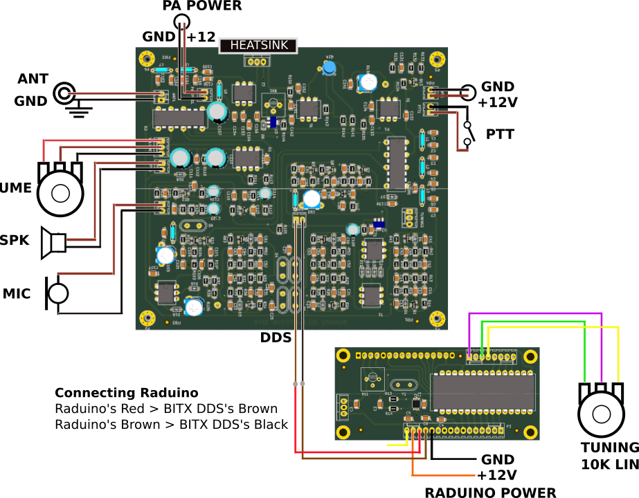
Link to HF Sigs site: https://www.hfsignals.com/index.php/2017/11/23/wiring-up-the-bitx40/
http://shop.qrp-labs.com/index.php?route=product/product&product_id=88
Master Sketch on Farhan’s Github: https://github.com/afarhan/ubitx
Updated Sketch (for uBitx 4 but works on v3 also): https://github.com/afarhan/ubitx4
CEC Firmware from KD8CEC (works on all versions of the uBitx): V1.2000 Firmware: http://www.hamskey.com/2019/04/release-cec-firmware-v1200-for-ubitx.html (also links to uBitx Manager).
CEC Firmware V1.1 (includes Nextion LCD display): http://www.hamskey.com/2018/09/ubitx-firmware-cec-version-11-release.html
CEC guide to upgrading firmware: http://www.hamskey.com/2018/01/how-to-upgrade-ubitx-firmware.html
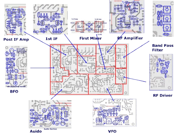
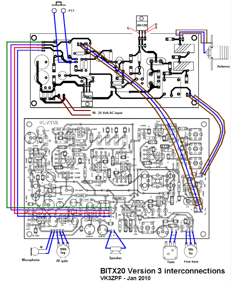
My Original Bitx 20 (v3) from Sunil
I have been having fun with the JA2NKD Arduino, AD9850 and 2.2″ TFT VFO – destined for use with once of my Bitx40s. I also notice that using a similar circuit Matsuura Ryuu has made available the code for his RF Analyzer incorporating a signal generator, power meter, frequency response visualizer and HF antenna analyzer – this looks very interesting. My initial testing with both sketches and my breadboard prototyping looks very promising (see below). I also noticed that another Japanese amateur, Akio Mizuno JA2GQP, is offering a similar VFO circuit but this time replacing he AD9850 with and si5351a (using one of the spare clocks this si5351 variant also includes a BFO – very nice and similar to something I have seen Paul Darlington M0XPD do with the Si5351a (details on his blog and also see here for the production version: http://m0xpd.blogspot.co.uk/2015/04/si5351-shield-production-pcbs.html
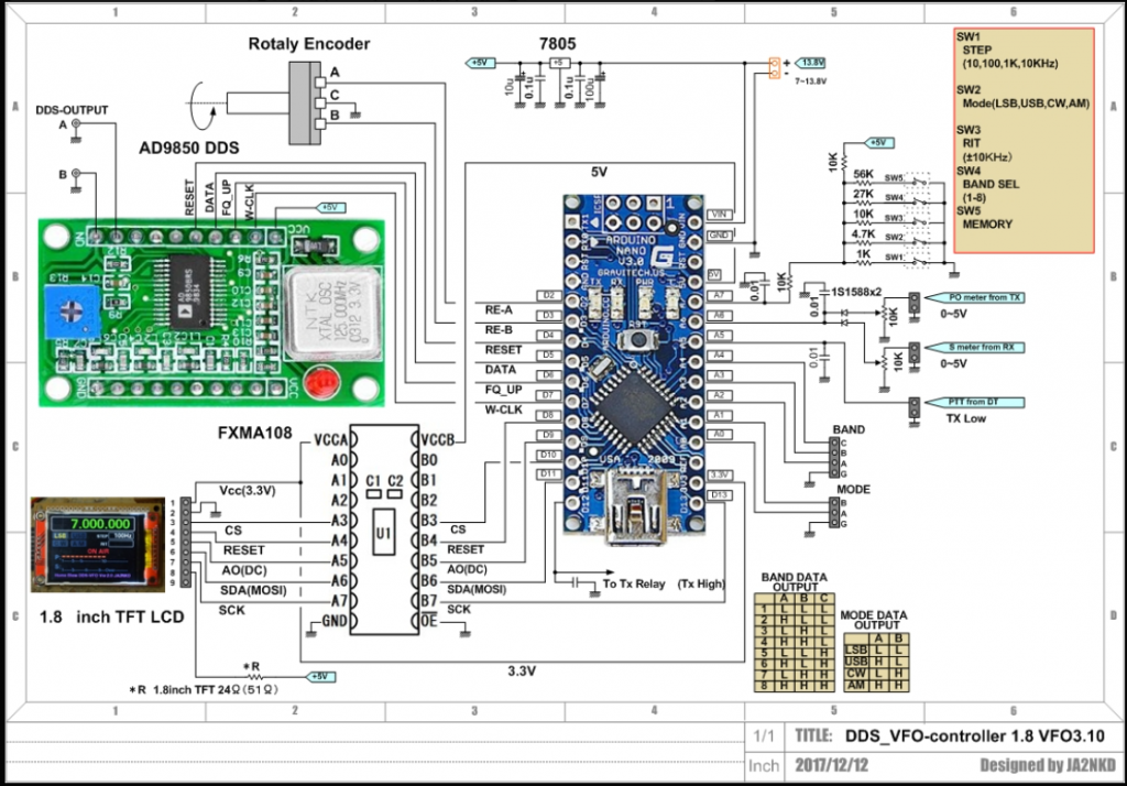

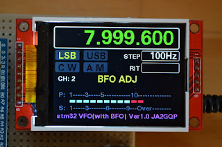
An updated version with touch panel display is here: Homebrew Radio JA2NKD: VFO Controller 8.0 (Aruduino Due with touch panel) (30 Jun 2020)
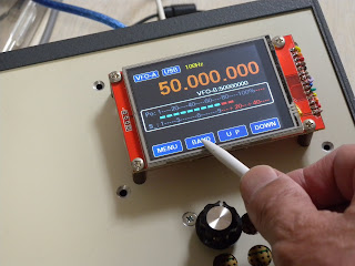
More details to follow including the schematic and Arduino sketch

Tuesday evening was my first time out with the unit was returned from Bulgaria with the RX and TX lines split (tiny SMD link!) new configuration since Anthony’s help with the mast top box.
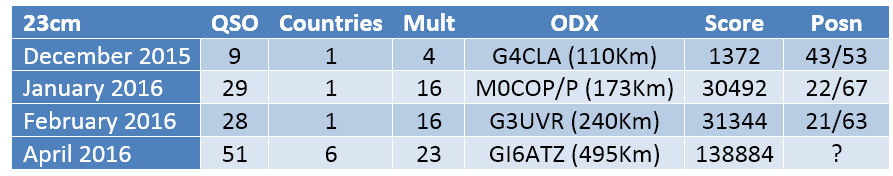
This meant an increase from the 2W used previously to a whopping 10W and hopefully an increase in RX NF with the removal of the superfluous diode from the RX line. The results were not to be disappointing. As a reminder the image below is the summary of my three previous attempts on 23cm UKAC. Note that I was not on air on 23cm in March 2016 as the transverter was on an extended routing through Eastern Europe making its way to and from SG Lab in Bulgaria! The squares show Red – December 2015, Green January 2016 and Blue February 2016.

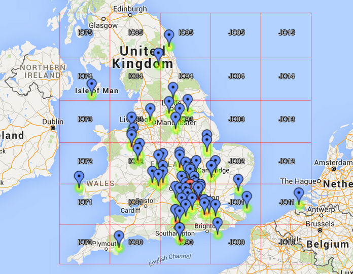
The Map below shows the results with the new setup in April 2016. FT991, SG Lab 23cm Transverter. PE1RKI amp at 10W. 25 Ele yagi. . 6 Countries: England, Wales, Northern Ireland, Isle of Man, Guernsey and Netherlands. 23 Mults, 51 QSO, total score 140,000. Best DX GI6ATZ.Rats worked: LZE, LRQ, SAT, WJG, JRY, sorry didn’t hear ZRG:

Stop Press: The results are out and I was placed 10th out 70 AL stations in April
UPDATE MAY 2016 – 23cm UKAC IO91OQ again
Keeps getting better from the high perch in IO91OQ. A few mast support issues tonight but rectified with a rope and a handy fence post – the drive on mast plate is a write-off though (which is a pain as I was going to use it on Sunday!). Best night for me on 23cm, Good signals from up ‘North and delighted to work PE1EWR in the Netherlands. Rats worked: RUL/P, WCB/P, SAT, LRQ, LZE, JRY, WJG, DFL. ODX was G8PNN in IO95. Final tally was IO71,74,80,81,82,83,84,90,91,92,93,94,95,00,01,02 and JO11. Sorry to have missed both 70 and 03 which I could see were on from KST messages. Only the odd squeak from GM but never workable – not through want of trying.

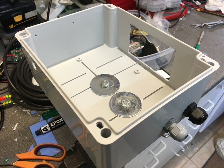
The 23cm mast top box is now almost completed with many thanks to Anthony for help putting it together. The unit now comprises an SG Labs transverter (2W output( and a PE1RKI amplifier. With 2W input the amp gives 40W output, with a 6dB pad on the transverter output the 28V amplifier gives 10W output for 500mW in. This configuration will give me 10W for the RSGB UKAC AL section and by removing the pad I can have 40W for UK Microwave Group contests.
The RF relay is a little Swedish made GHz SMA relay (branded Philips) whilst DC voltage is sequenced to the relay, amplifier bias (12V) and the the transverter PTT using a W6PQL sequencer and a band of 12V miniature relays. The 28V main voltage is supplied to the amplifier contentiously.
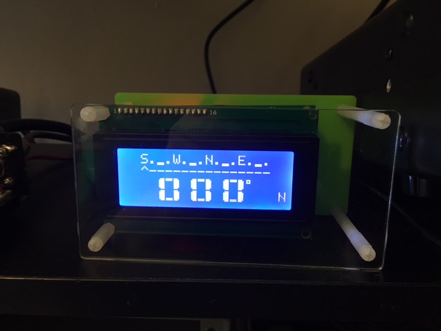
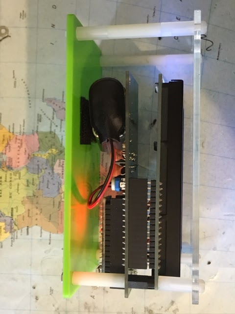
At the base of the mast is a small control box containing the PTT interface, 28V PSU (DC to DC up convertor from 12V) and the 12V supply. The control cable provides: 28V, 12V, PTT, Ground, and a Serial connector for arduino (not yet connected). In due course there will be an Arduino Nano in the mast top box and another in the control box. The Arduino will provide the following information from the mast top box to an LCD screen on the control box; 28V and 12V voltage monitor, current drawn by amp on peaks, Transverter Fwd Power, Reflected Power, SWR, Amplifier Power Output.
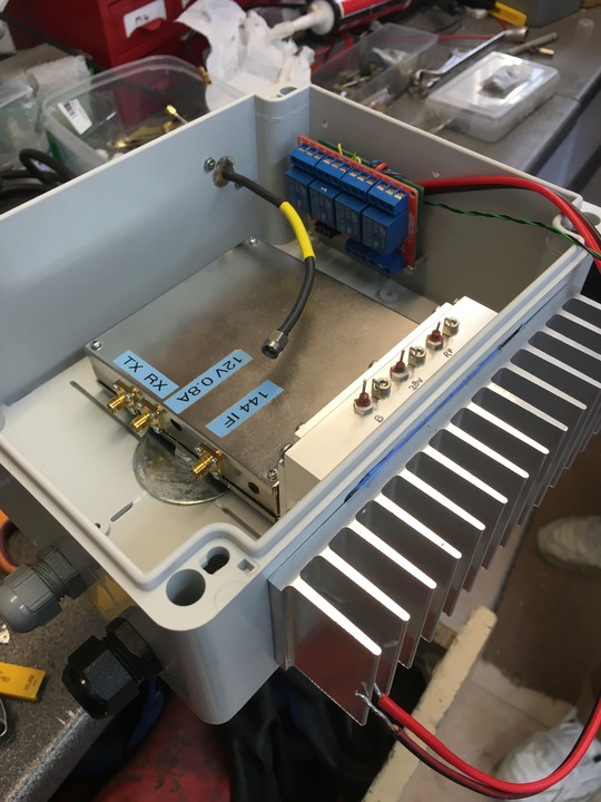
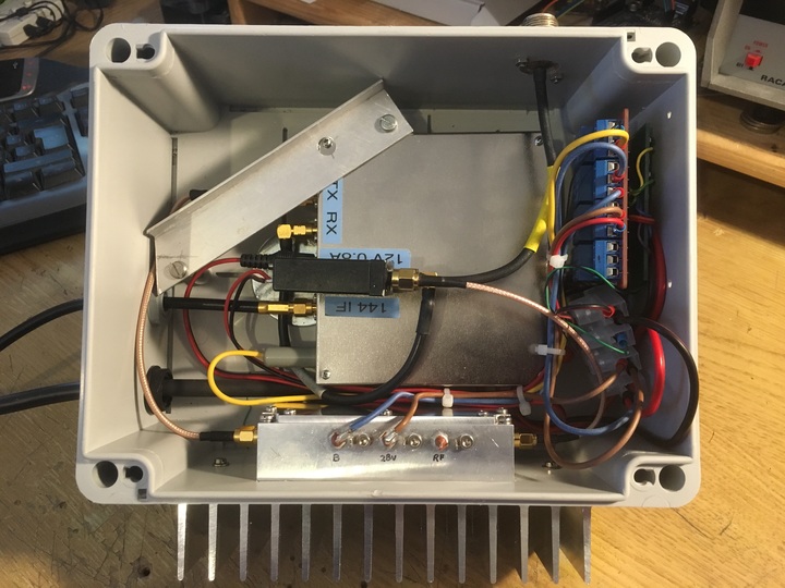
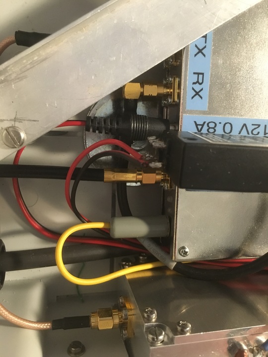

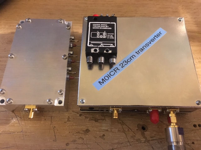
Here is the transverter, PE1RKI amplifier and the 28V Failsafe Philips SMA Coaxial relay.
Subsequent QSO’s with Dave followed on CW and USB


Radio: Kenwood TH-F7